
Slot Car Sensors
This page describes several slot sensor technologies. They are compliant with any kind of track brand (Scalextric, Ninco, Aurora...) and with Ultimate Racer.
- basic infra-red or photo-resistor sensors
- enhanced infra-red sensor
- enhanced dead-strip sensor
All schematics have been built with Eagle.
Reliable slot car detector, especially for 1/32 scaled Formula 1.
Contact support@uracerweb.org for any commercial use of the designs.
Download Eagle project.
Basic Infra-Red & Photo-resistor Slot Car Sensor
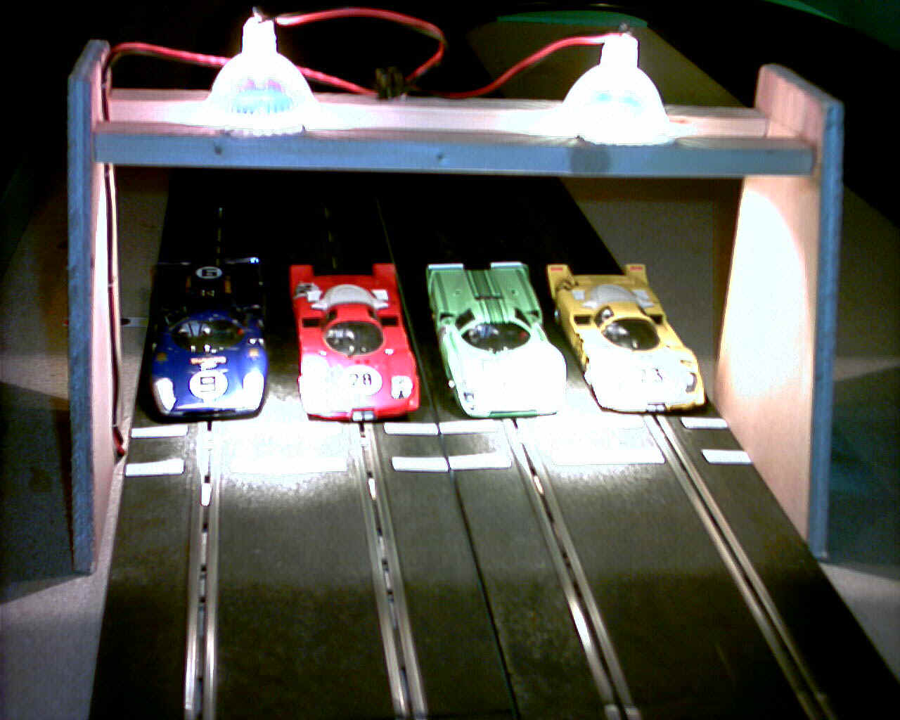
Light Bridge
The sensors are plugged into holes made in the track section or between the lane electrical contacts. Then a light is applied above the track section to light the sensors. A passing car blocks the light and a lap is detected.
One of the oldest and more used sensor technology. The sensor is either a photo-resistor or an infra-red sensor. The pin status is low the sensor is connected to is low when lit. When a slot car cut the light (sensor in shadow), then corresponding pin status goes high.
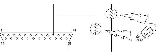
Schematic #1 : for a 2 lane sensor with 2 photo-resistors, 1 per lane. Photo-resistors are connected to pins 10 and 11 here.
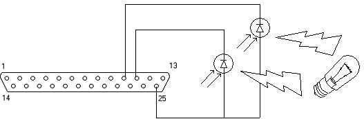
Schematic #2 : for a 2 lane sensor with 2 infra-red sensors, 1 per lane. Infra-red sensors are connected to pins 10 and 11 here.
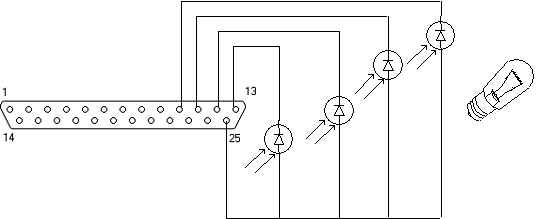
Schematic #3 : for a 4 lane sensor with 4 infra-red sensors, 1 per lane. Infra-red sensors are connected to pins 10, 11, 12 and 13 here.
Part list :
- 1 x photo resistor per lane : 10 kOhms OR 1 x infra-red sensor per lane : honeywell/SDP8436-003
- 1 x DB25 male parallel port connector.
- wires to connect sensors to parallel port connector
Note 1 : the infra red sensor specified above is very handy : its size is very small thus compliant the track section slot width. Nevertheless you can use different infra red sensor.
Note 2 : photo resistors reaction speed depends on the light strenght. Usually this reaction speed remains above 1 millisecond which is upper than the software accuracy => less reliability. The infra-red sensors reaction are much much much more faster!
Where to find these parts ? Depends of your country. Any electronic shop such as Radiospares, Farnell, Radioshack is OK. These electronic components are very very popular and cheap.
Enhanced Slot Car Sensor
This electronic circuit uses a trigger to amplify any slot car device detectors (RTDs, photo diods, bridges). It designs a 2 lane detector. Build it twice for 4 lanes, and so on.
This sensor increases the lap time detection duration making the detection more reliable on slow PCs.
Trigger value duration is based on (R3, C1) values for IR2 input pin, and (R4, C2) for IR3 input pin.
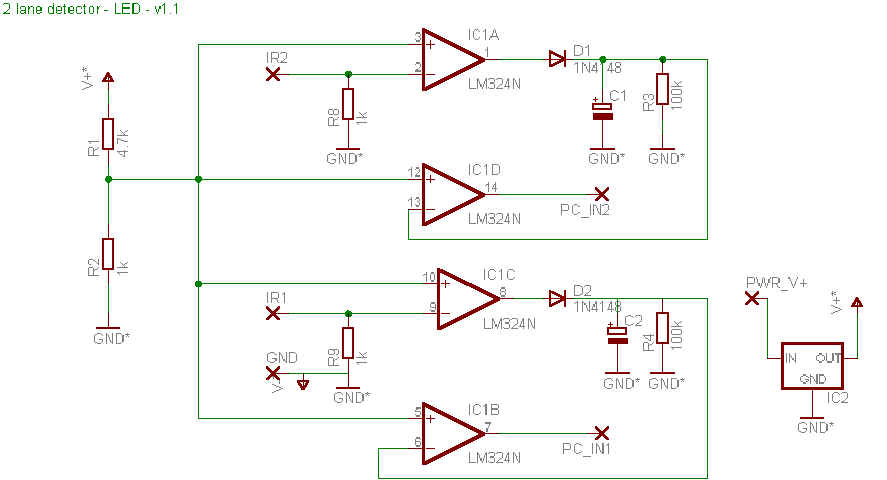
Schematic :
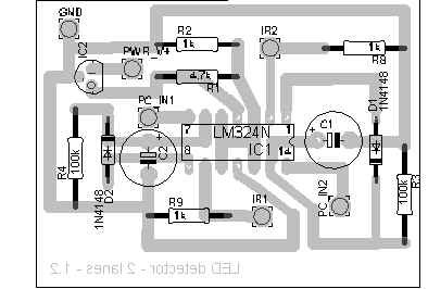
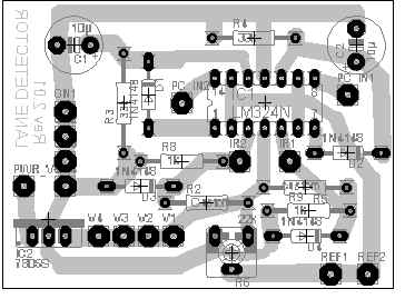
Placement :
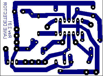
PCB
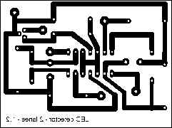
PCB real size : 60mm x 45mm
Part list
- IC1 : LM324 - 4 ampli ops
- D1, D2 : diod 1N4148
- IC2 : 78L05 - voltage regulator
- C1, C2 : capacitor 10µF
- R2, R8, R9 : resistor 1k - 0.25W
- 1x Parallel port connector
- R3, R4 : resistor 100k - 0.25W
- ribbon cable + standard cable
- R1 : resistor 4.7k - 0.25W
- photo transistors (optional) : honeywell/SDP8436-003
External connections :
- PC_IN1, PC_IN2 connected to one PC parallel port interface input pin (pins 1, 10, 11, 12, 13, 14, 15, 16, 17)
- GND connected to one PC ground pin (pins 18 to 25) and to external power supply (-) output.
- PWR_V+ connected to external power supply (+) output. Power supply voltage : 6V up to 12V
- IR1, IR2 external slot car detector. Either a photo diod/transistor or a LRD (10k) - see below
Detailed description :
Principles :
Each detector is based on 2 Aops in comparator mode. First Aop is used to detect any changes generated by a LRD or a photo diod. It generates an edge which is sustained by Cx capacitor. This is usefull when you race with Formula 1. With only 1 Aop, the edge width may be very short, often shorter than the PC pooling system => and in this case the PC detects nothing! Cx capacitor can be changed according to the PC pooling speed (depending on your system).
Detecting cars with LRD or photo transistor :
The external slot car detector can be a 10k LRD, a photo diod as described below (IRx and IRy corresponds to previous schematic IR1 and IR2 inputs) or any other slot car detector device :
External LEDs are required to light the LRD or the photo diod. They can be mounted directly into a bridge above the starting track.
V+ supply can come from the previous system (5V from the voltage regulator) or from an external power supply (6V voltage is OK).
I am using photo transistors honeywell/SDP8436-003. They are very small and they can be easely pasted on the rear of the track. They need an additionnal light or infra red to light them.
If you use paraport to detects slot car events, external device output level does not impact detection (either high or low). Paraport detects changes and generates interrupts when changes have been detected (from high to low... and low to high).
How to connect the honeywell/SDP8436-003 ?
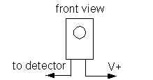
Front view.
Using an external bridge (like DS300) :
If you're using an external bridge detector like a DS300, please read carefully. The comparator threshold is given by following formula :
threshold = (R2/(R1+R2)) * 5V = 0,9V
So if the bridge level low is below 0,9V and its high level above 0,9V, the system will work. The DS300 has a low level around 2V, and a high level around 5v.
So use following formula to calculate the new value for R1 :
R1 = R2 * (5V + threshold) / (5v - threshold) => will set the threshold voltage between 5V and bridge low level.
For DS300, low level is around 2V :
R1 = (4,7k * 7v) / (5v - 2v) ~ 10k (10k instead of 11k is more common...)
Configuration with Ultimate Racer :
If you play with Ultimate Racer the pin number you solder the PC-INx outputs should be specified in the hardware parameters. Ex : if a detector is soldered on pin 12 and the other one on pin 13 on LPT1, specify it as follow
| Enabled | Event | Param1 | Param2 |
| Actif | LPT - Detects slot car - Lane #1 | LPT1 | 12 |
| Actif | LPT - Detects slot car - Lane #2 | LPT1 | 13 |
Enhanced Dead Strip Sensor
This electronic circuit uses a trigger to amplify any slot car dead strip sensor. It designs a 2 lane detector. Build it twice for 4 lanes, and so on.
This sensor increases the lap time detection duration making the detection more reliable on slow PCs.
Trigger value duration is based on (R3, C1) values for IR2 input pin, and (R4, C2) for IR3 input pin.
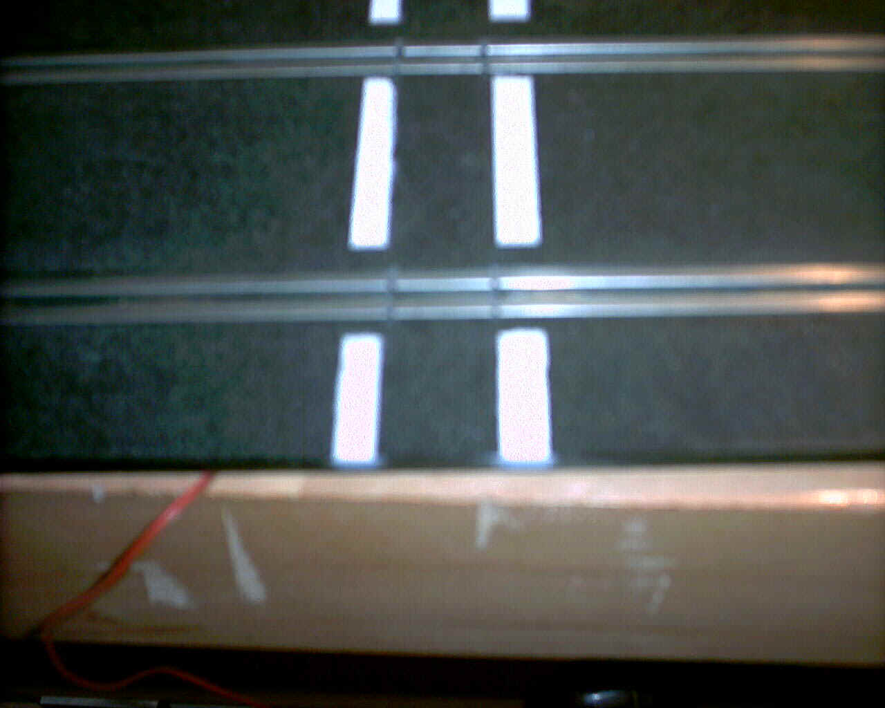
This sensor requires some track section rework, but the result is clever : just few centimeters of isolated track section. Quite invisible. That's the one I use.
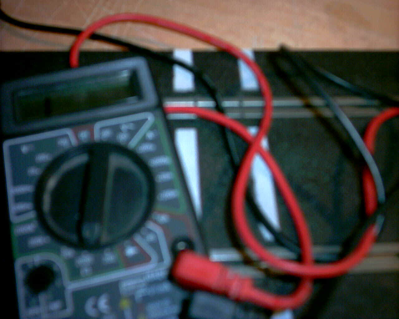
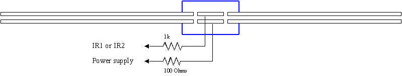
The dead strip :
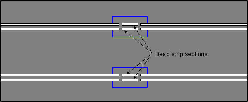
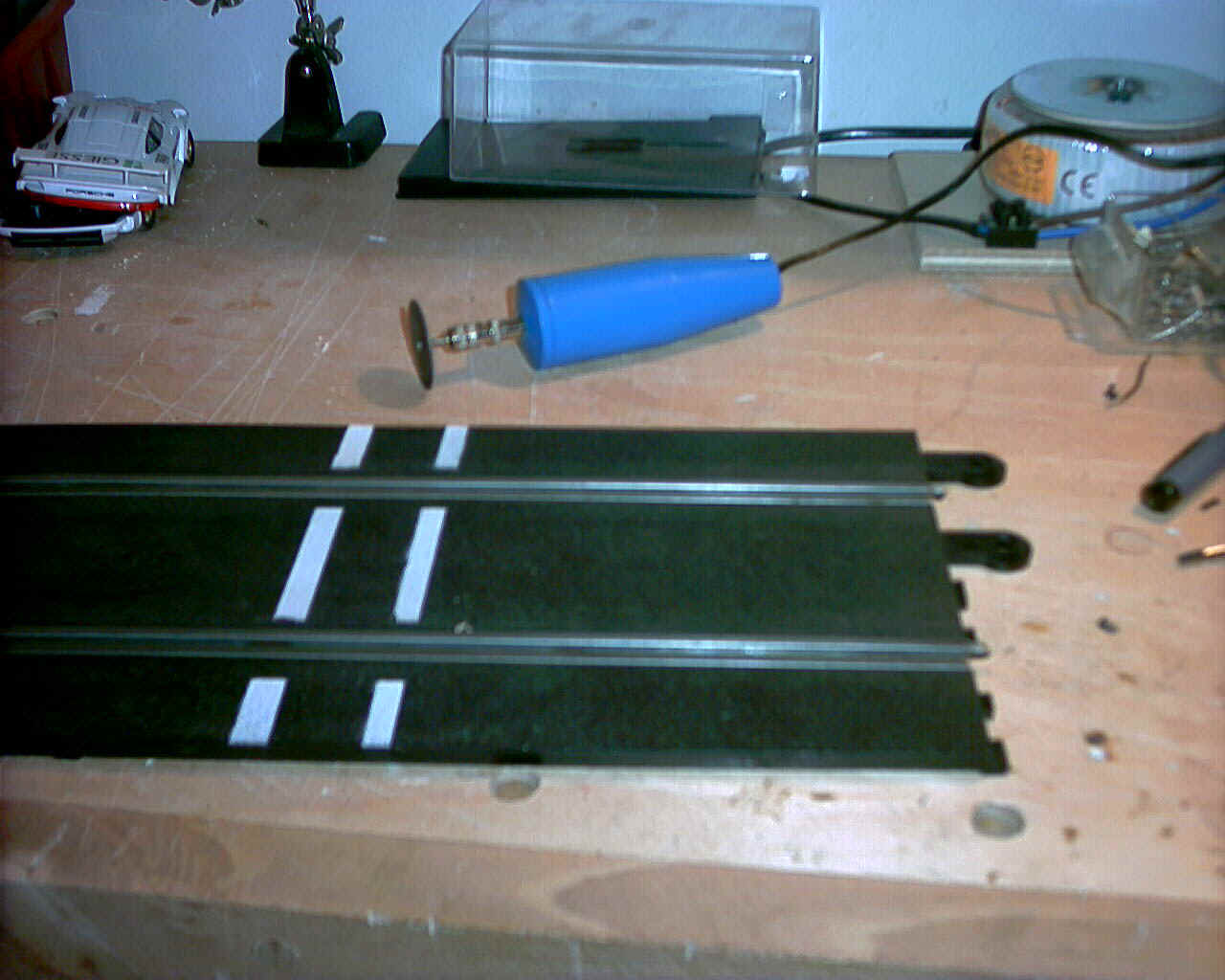
The trick to build the dead strip : a mini electrical drill to cut the track section electrical contact :
Clean up the dead strip when the cut is complete. Make an electrical test to insure that no more iron dust remains between the dead strip and the track section. Trick : use a magnet to capture and remove this remaining iron dust. Then solder 2 x 2 wires to keep electrical continuity around the dead strips.
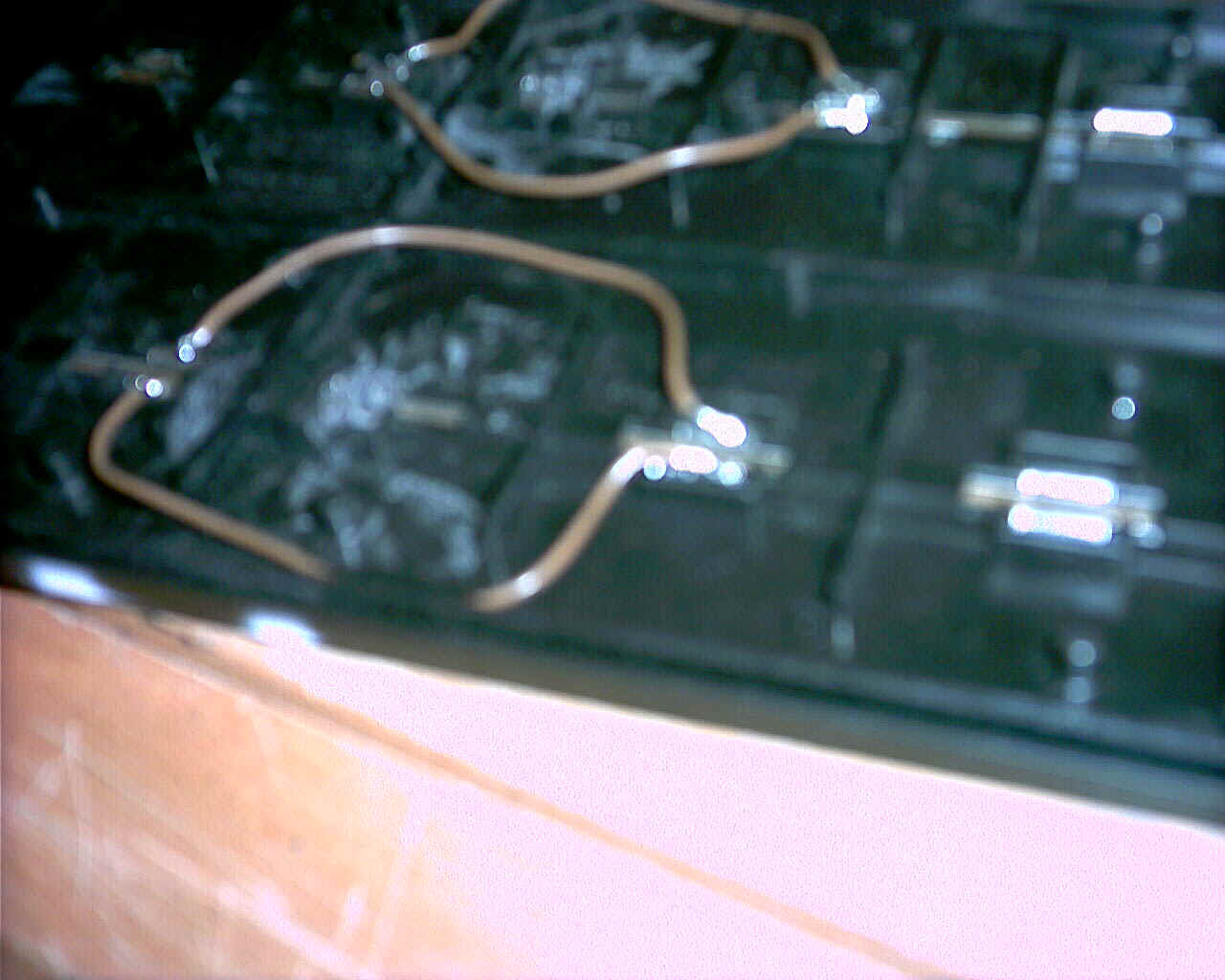
And now you're ready to connect the dead strip to the electronic sensor.
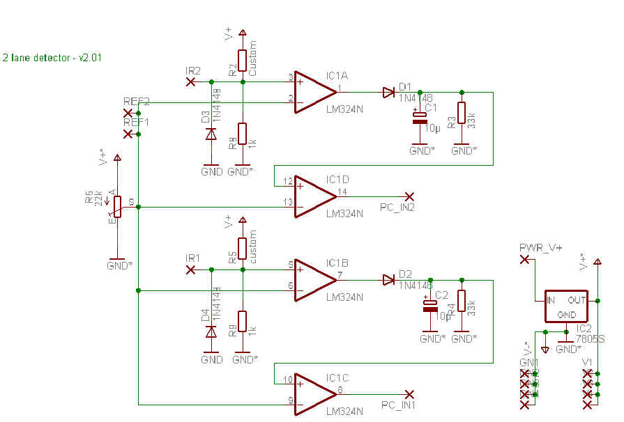
Schematic :
Placement :
PCB :
Part list :
- C1, C2 - 10µ capacitor
- D1, D2, D3, D4 - 1N4148 diods
- IC1 - LM324N
- IC2 - 7805S
- R2, R5 - Custom => 10k
- R3, R4 - 33k
- R6 - 22k, variable resistor
- R8, R9 - 1k
- Parallel port connector - DB25 male X 1
- 8 x resistors for dead strip - 4 x 1k + 4 x 100 Ohms
External connections :
| PC_IN1, PC_IN2 | connected to one PC parallel port interface input pin (pins 1, 10, 11, 12, 13, 15 |
| GND | connected to one PC ground pin (pins 18 to 25) and to external power supply (-) output. |
| PWR_V+ | connected to external power supply (+) output. Power supply voltage : 6V up to 12V |